Practically speaking, capacitive sensing techniques are typically used to create buttons without a mechanical switch. Basically, when you design your PCB you include special traces that do the sensing. When a finger, or a nose or whatever gets close to the sensing trace, the software in the micro controller senses a shift in the capacitance of the trace. This shift in capacitance is what the micro uses to determine if the user has activated the "button". These sensors can take many forms. Usually they are hidden below a layer of plastic, with some sort of icon printed on it. I have even seen sensors made of conductive ink that has been drawn on!
Chances are you own something that utilizes a capacitive interface. For example, the iPhone uses a thin, transparent membrane embedded with an array of tiny electrodes that it uses to sense where your finger is at on the display. If you fool around sometime, you can actually get the iPhone to detect your finger even if its not physically touching the screen. This is the beauty of capacitive sensing. There is a lot of "tunable" parameters that you can change to influence the behavior of the interface.
There are gobs of cool applications out there, the possibilities are almost limitless!
Read on to discover how it works!
How does it work?
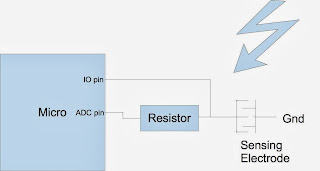
Typically there are two main methods of implementing capacitive buttons. The first method can be implemented on just about any micro controller with an Analog to Digital Converter or ADC. Most micros have at least one. The ADC is a tiny internal peripheral in the micro that can measure the voltage on the sensing electrode. It basically takes a quick "snapshot" of what the voltage is on the electrode. Since you can't directly measure the capacitance of the electrode with an ADC, the firmware must take a series of ADC "snapshots" to get an idea of how the capacitance has changed. The basic theory of operation is this:
Step 1: Charge the electrode. The firmware can use an IO pin or change the ADC pin to an output and apply a voltage to the sensing electrode. This voltage must be turned on for a few hundred micro seconds to milliseconds to fully charge the electrode.
Step 2: Turn off the IO pin and start rapidly taking "snapshots" of the voltage on the sensing electrode using the ADC. If the firmware can take the readings fast enough, you will notice that each reading of the ADC will decrease.
Step 3: The secret to capacitive sensing is the speed at which the ADC readings decrease. The larger the capacitance, the slower the ADC readings will decrease.
For example: Most of the time, the user will not have a finger near the electrode. The ADC readings may look like this.
| #1 | #2 | #3 | #4 | #5 | #6 | #7 | #8 | #9 | #10 |
| 1000 | 800 | 500 | 100 | 0 | 0 | 0 | 0 | 0 | 0 |
But when someone starts to touch your beautiful circuit with their hairy fingers it may look something like this.
| #1 | #2 | #3 | #4 | #5 | #6 | #7 | #8 | #9 | #10 |
| 2000 | 1500 | 1200 | 1000 | 800 | 500 | 200 | 100 | 0 | 0 |
Arduinos are also capable of implementing capacitive sensing. See http://playground.arduino.cc//Main/CapacitiveSensor?from=Main.CapSense for library information.
The second capacitive sensing implementation requires a specialized micro controller with built in hardware that is specially designed to sense capacitance. These features are fairly common with larger micros. Larger Microchip micros and Cypress SOCs have this option. Typically this implementation uses two internal clocks to detect shifts in capacitance. One clock will tick at a known rate, while the other clock is connected to the capacitive sensor. When the capacitance increases, the second clock will slow down. The first clock is used to detect this "slowness".
Hope that helps feed the imagination, keep wiggling those pins!


No comments:
Post a Comment